2017-12-02T02:23:17+00:00
Reserved.
Reserved.
The PCB assembly is described in 2 stages, the first covers the majority of the components before first test and the second stage after it's attached to the levitation assembly, at which point you'll need to be much more careful of flying screwdrivers...
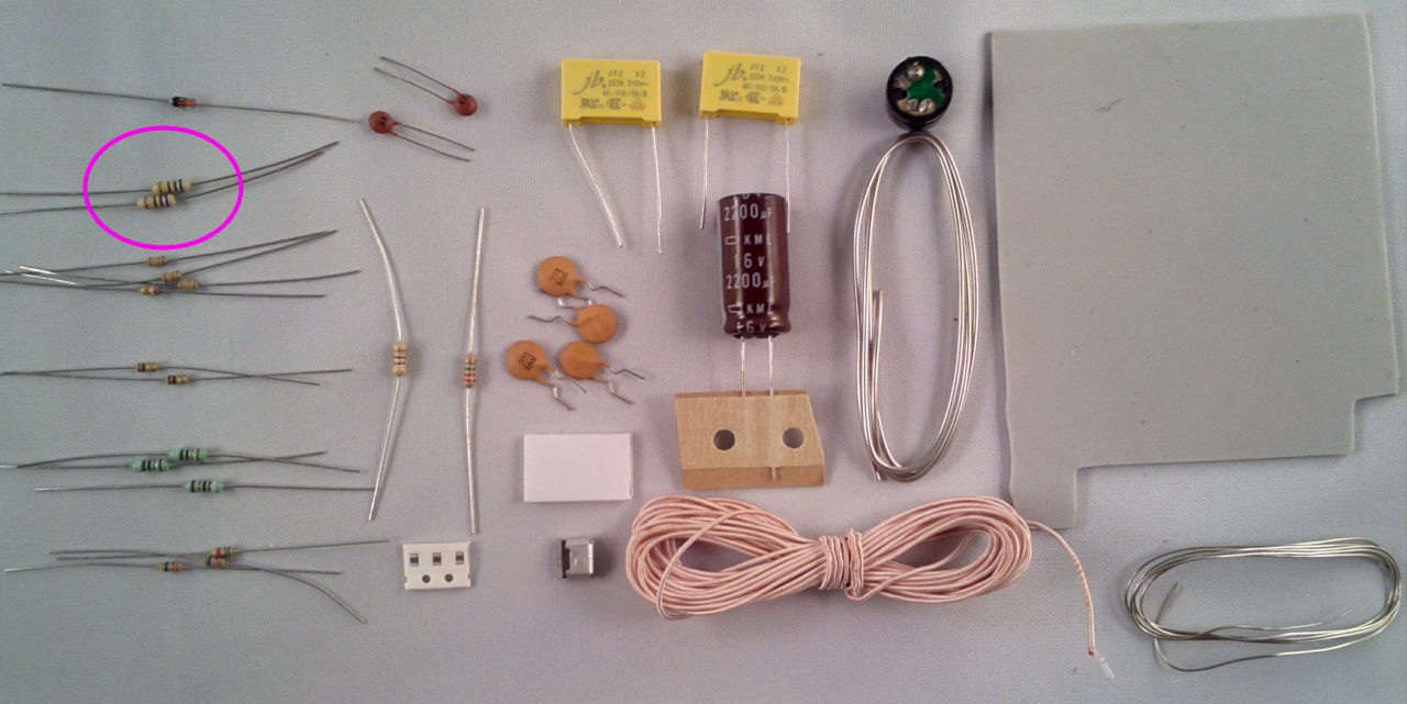
The exact order of assembly will depend on the preference of the builder but convention is to fit the resistors/diodes first followed by capacitors, transistors and finally the ICs, USB socket/power conectors in that order. Use the thin solder for the small components and the thick solder for joining the PCB to the levitation module.
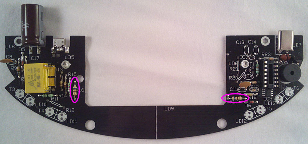
Starting with the resistors, take the 2x 680R (blue grey brown) resistors and fit them into the locations marked R16 and R17:
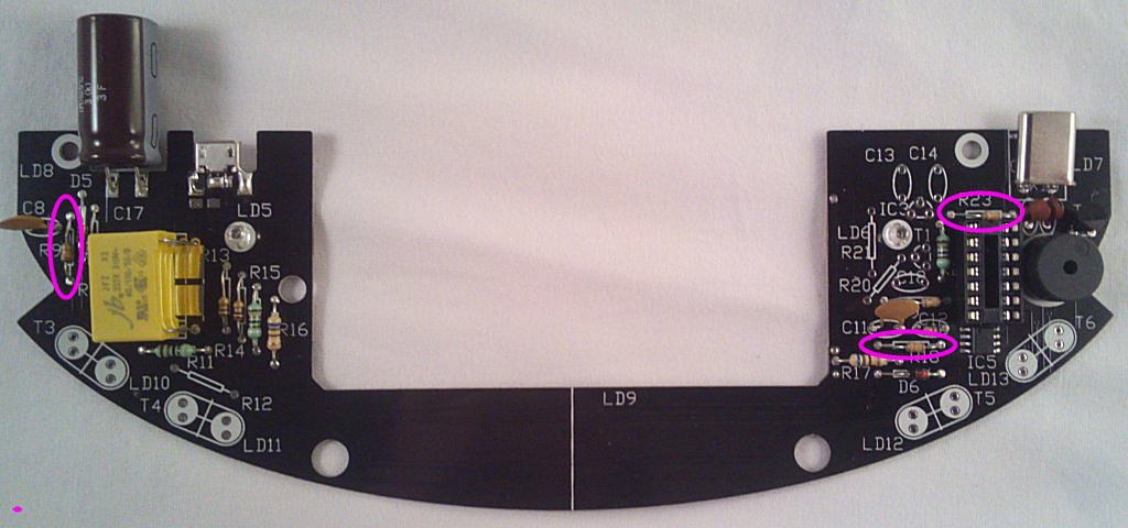
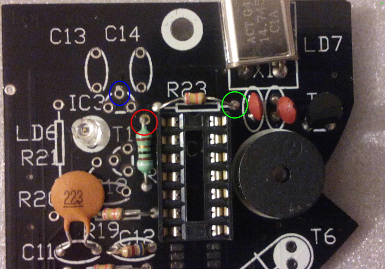
Take 4x 24k (red yellow orange) resistors and fit them into the locations marked R9,18, 19 and R23:

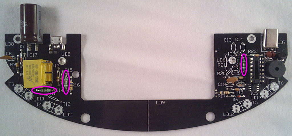
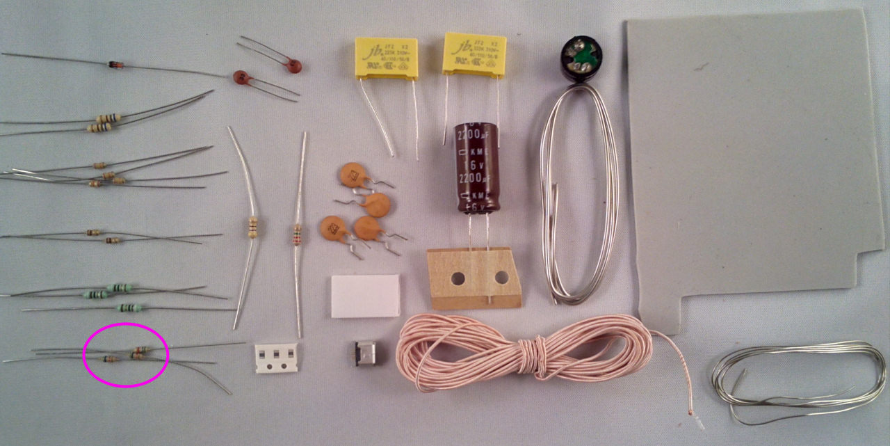
Now the 2x 1r1 (brown black gold gold) resistors, fit them into the locations marked R13 and R14:

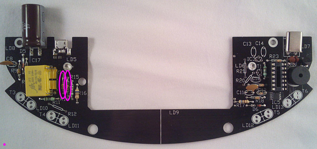
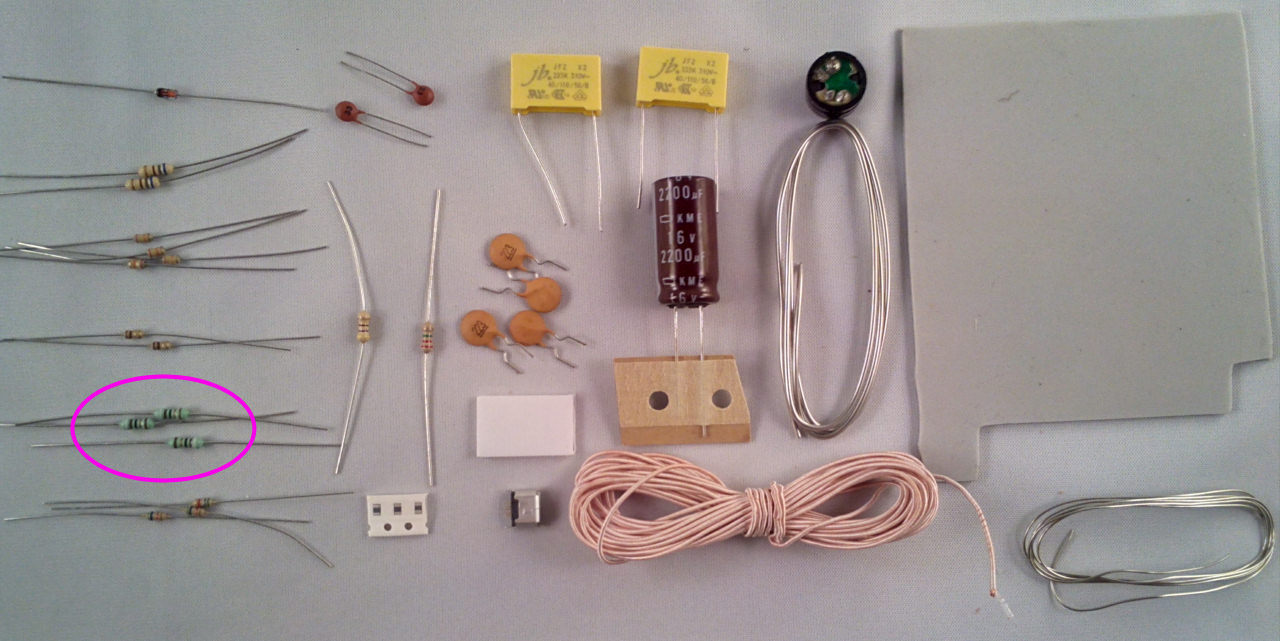
And the 3x 91R (White brown black black) resistors, fit them into the locations marked R11,15 and R22:
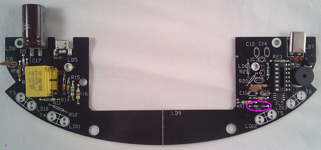
For now you just need 2x 5k6 (green blue red, the third is used later) resistors, fit them into the locations marked R10 and C12 (yes):
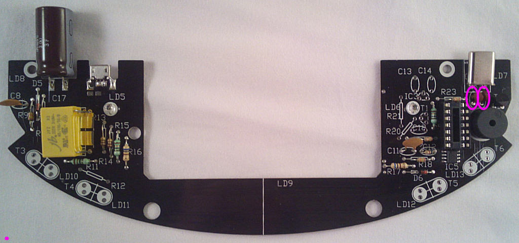
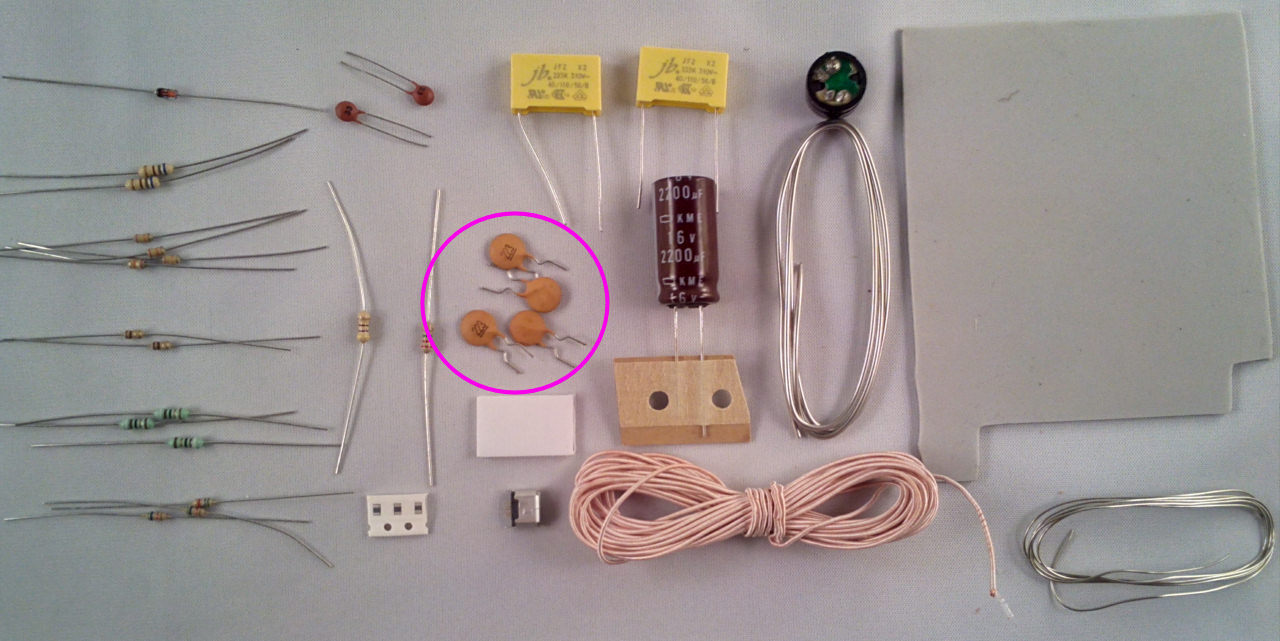
That's all of the resistors for now - next some capacitors. Take the 2x small ceramics marked 220 or 22p and fit them in the spaces marked C15 and C16:
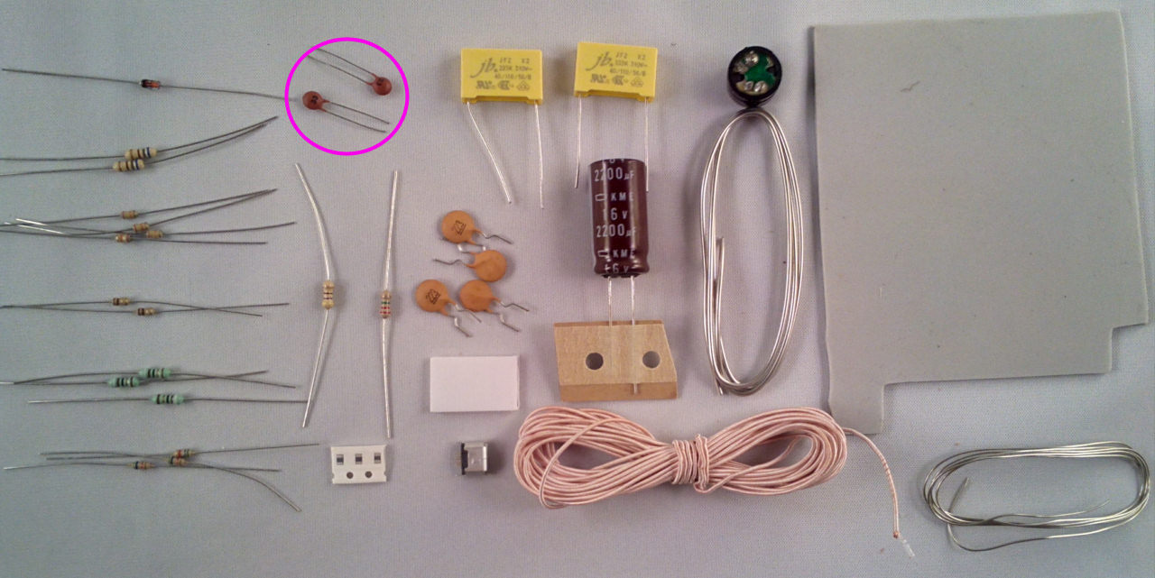
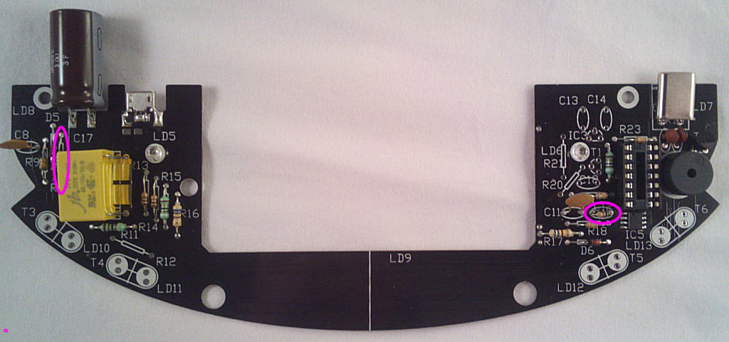
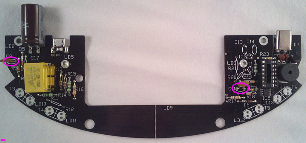
Take 2x brown ceramics marked 223 and fit them in the spaces marked C8 and C11:
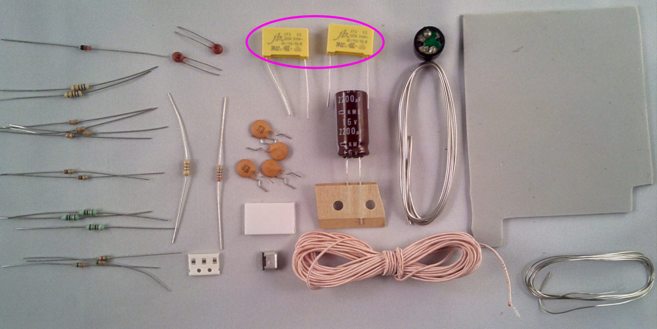
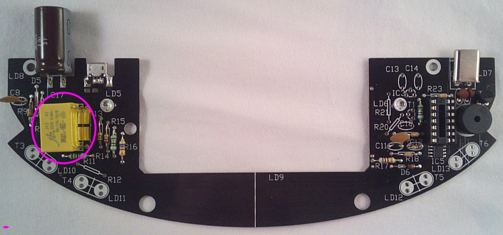
The 2 large yellow coil tank capacitors are next, fit them in the spaces marked C9 and C10:
They are connected together so it doesn't matter which order they are stacked in as long as they're flat against the PCB.
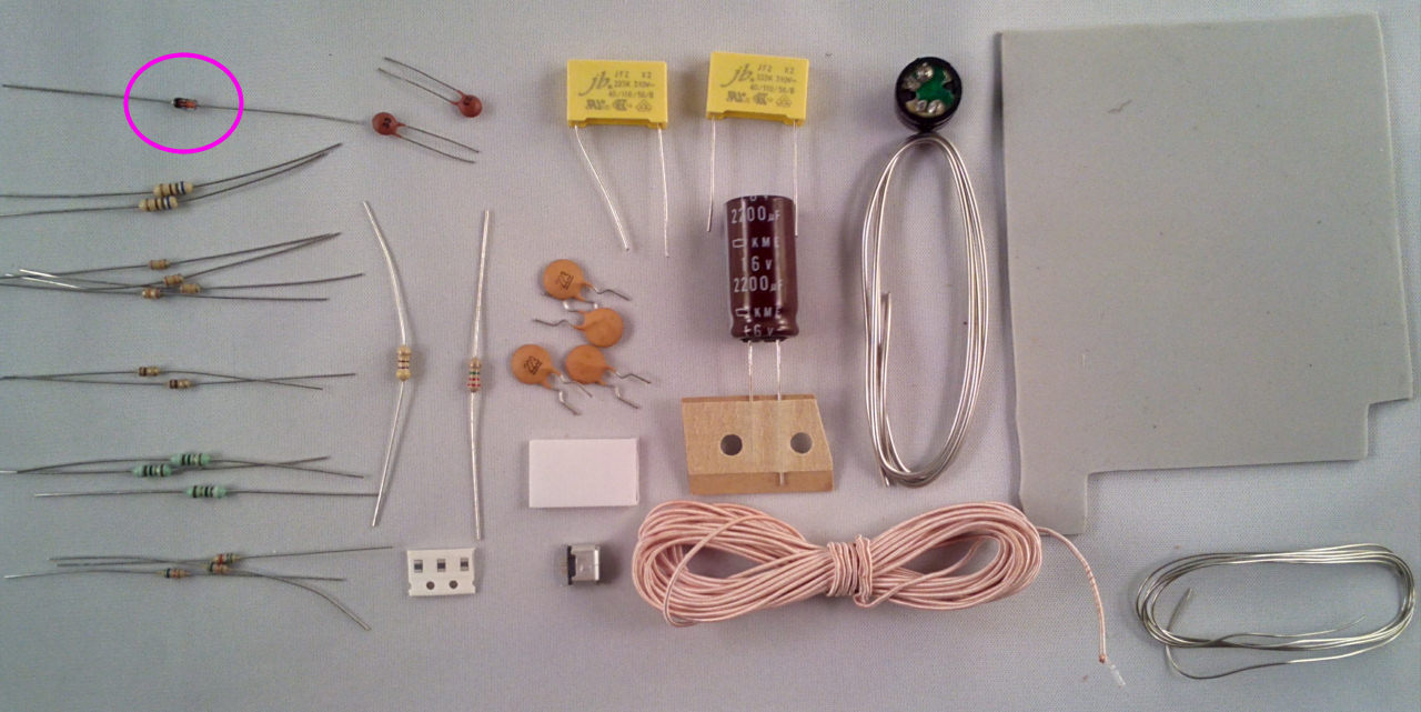
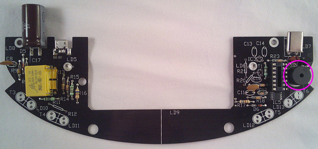
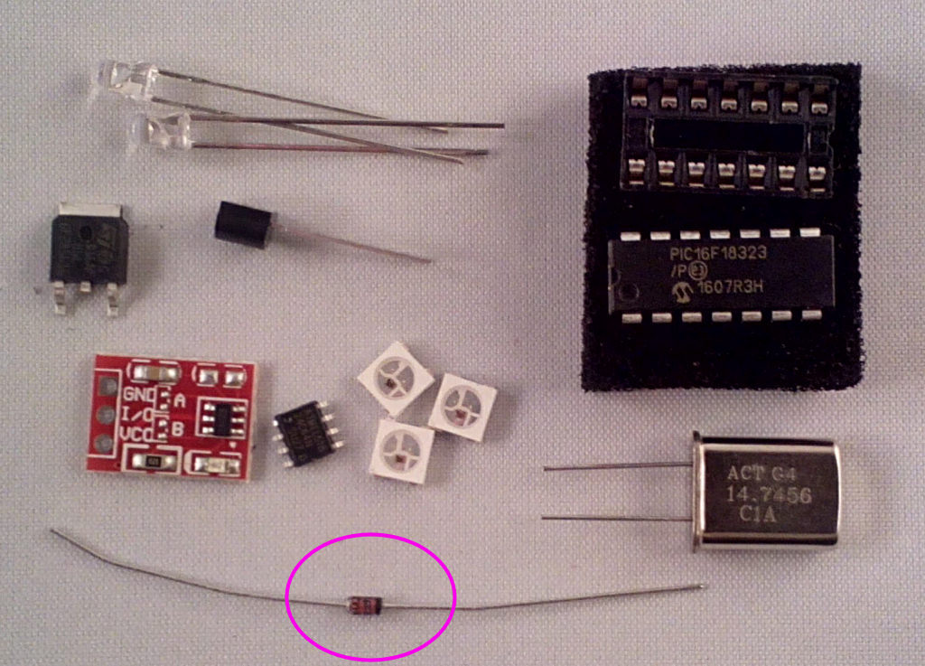
Now the zener diode D6, make sure it's fitted with the black band facing left:
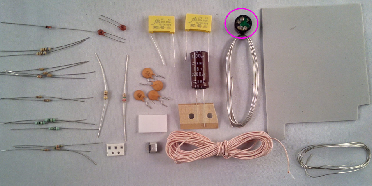
Speaker LS1, the + points to the top right:
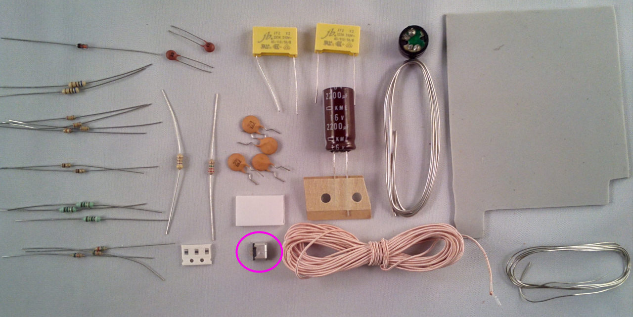
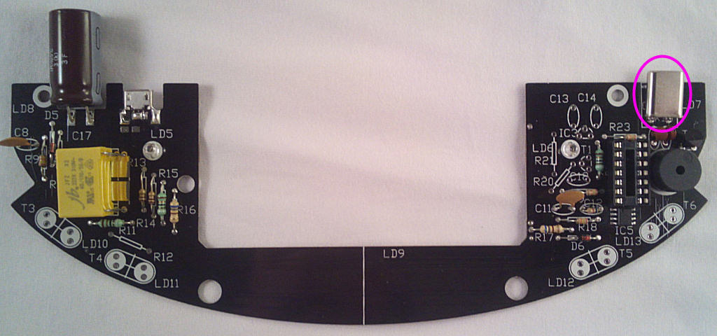
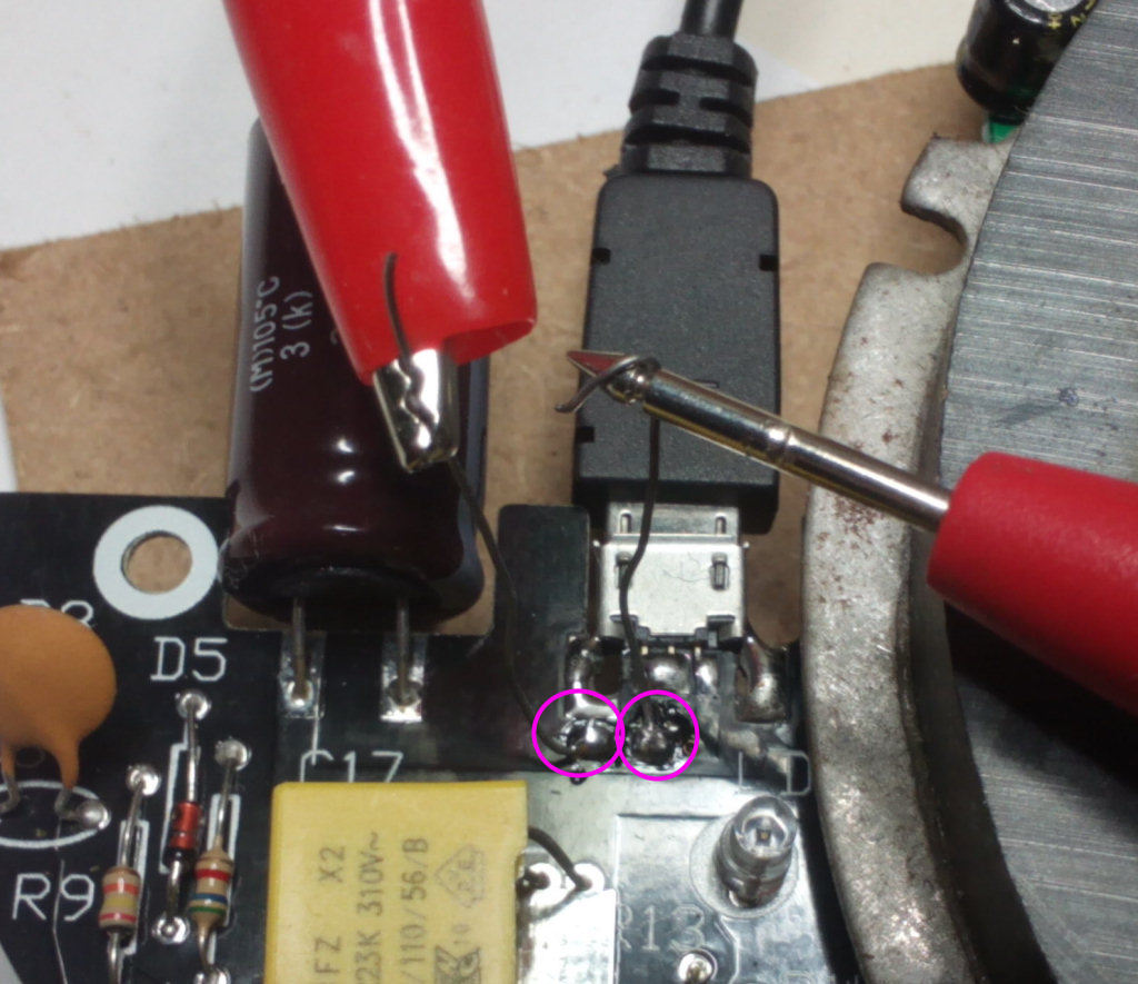
The USB socket - it's fitted so the edge of the PCB sits between the 2 rows of pins, allowing them to be soldered to each side of the board. The 3-pin row is on the top side:
Solder the pins on both sides of the board and bridge the socket case to the board as shown - be careful the solder doesn't end up in the socket though.
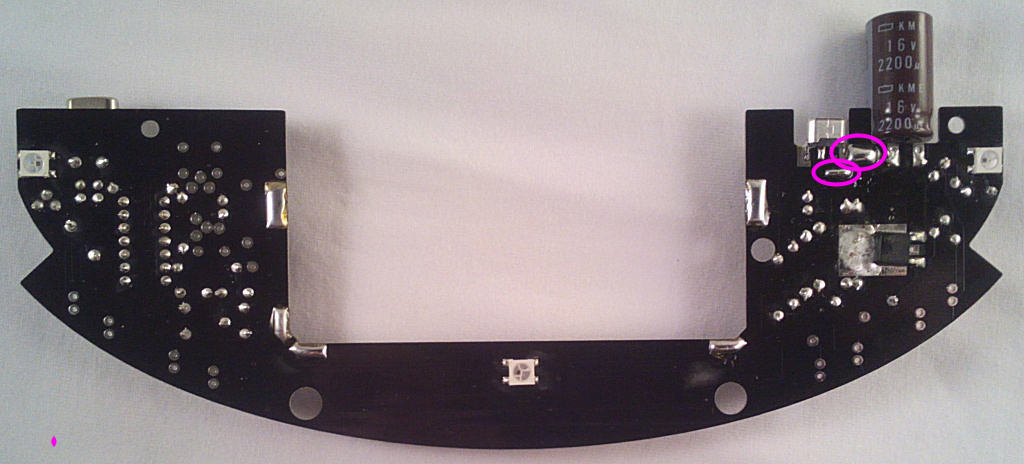
Bridge these pads with solder or component wire offcuts:
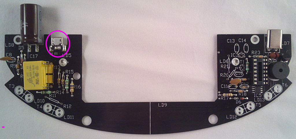
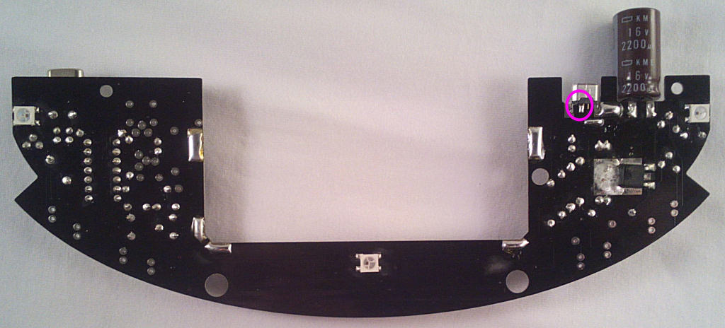
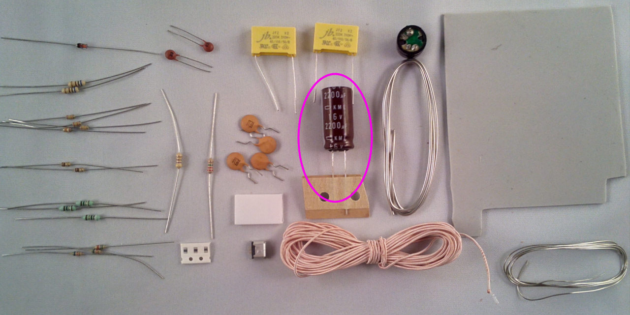
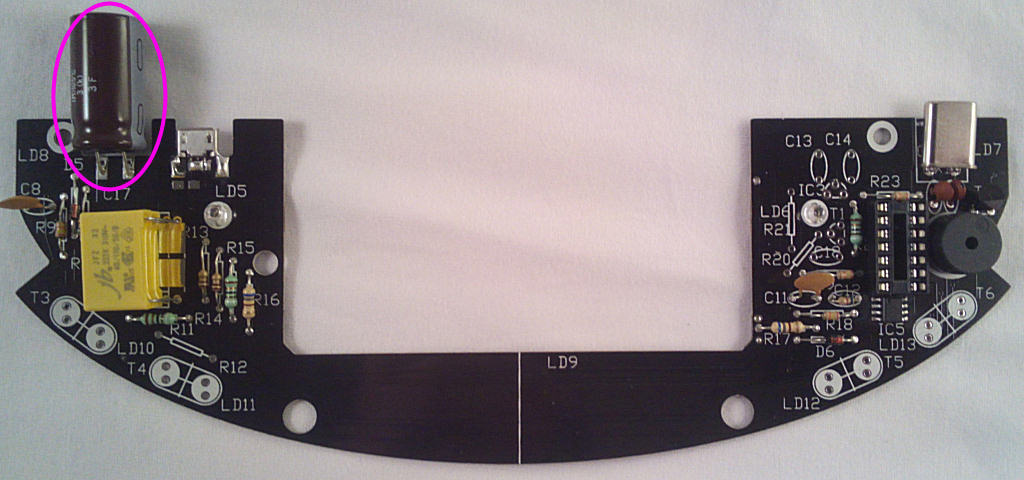
Now the last component from bag1 for now - the 2200u electrlytic capacitor. It's polarised so make sure the white band faces right:
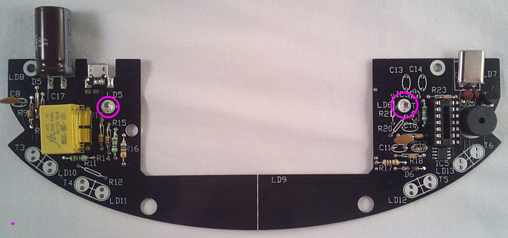
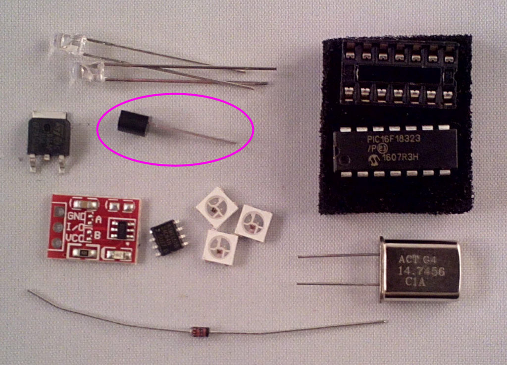
Bag 2 components next, starting with D5, the black band faces down:

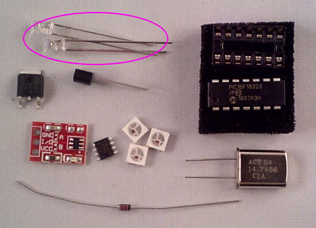
Then the 2x IR LEDs, LD5 and LD6. The SHORT lead points to the TOP of the board for both LEDs:
The 2n7000 speaker driver, T2

The socket for IC4 - don't fit the IC yet though:
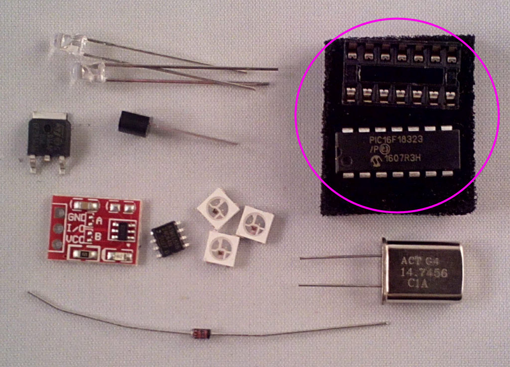

Last part on this side for now is the crystal X1:

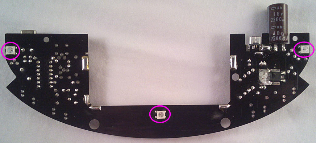
Time for a few surface mount parts, starting with the RGB LEDs LD7,8 and 9. The marked corner faces bottom right for LD7 and top left for LD8 and 9:

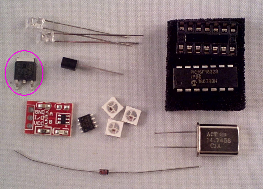
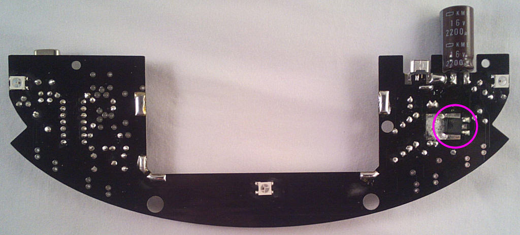
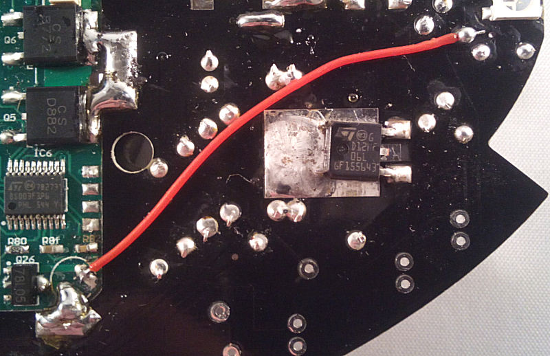
The coil driver transistor T7. Solder the tab and the 2 outer legs, the centre leg isn't used as the connection is made via the soldered tab. You did solder it?.
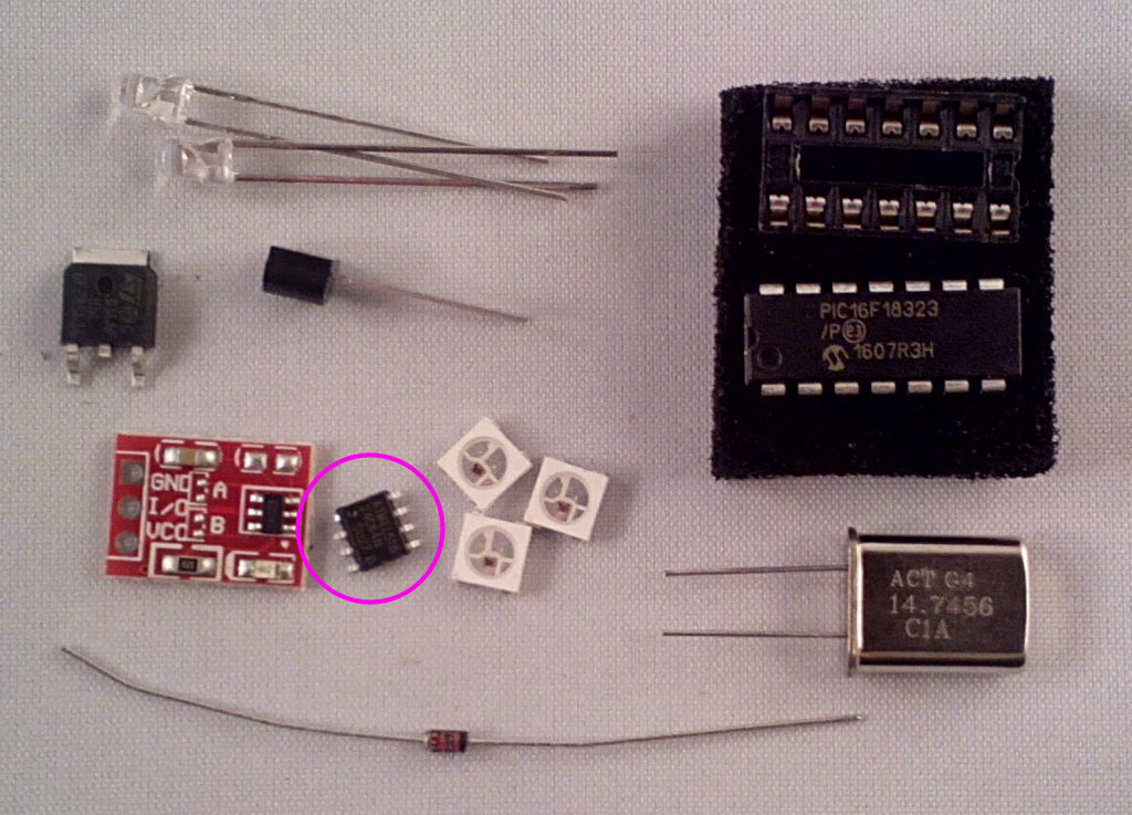
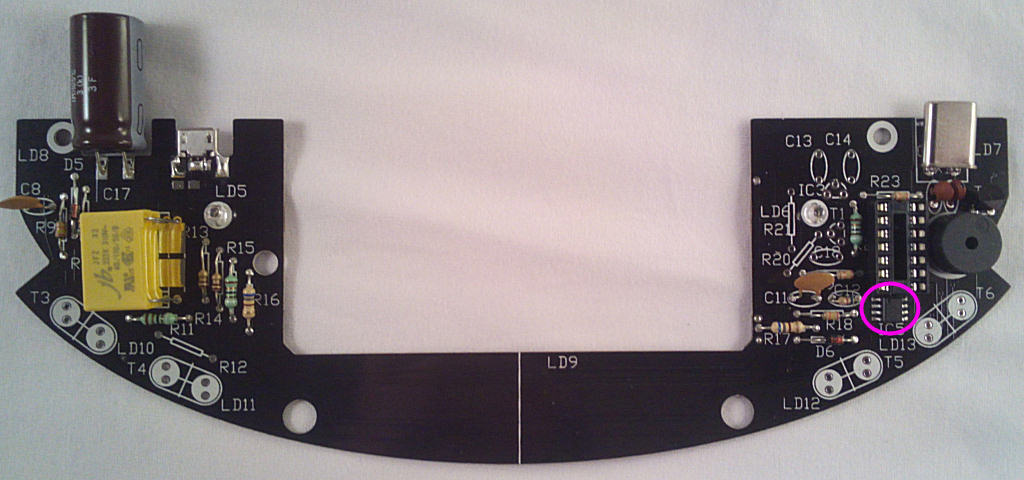
Finally for now the small EEPROM memory (24c64) IC5, this holds program updates for verification before they're written to the microcontroller. The pin 1 mark faces UP (some ICs have a bevelled edge to indicate the pin 1 side, that faces left if so):
Remove the 15V socket and any tagged-on components from the levitation module if fitted:
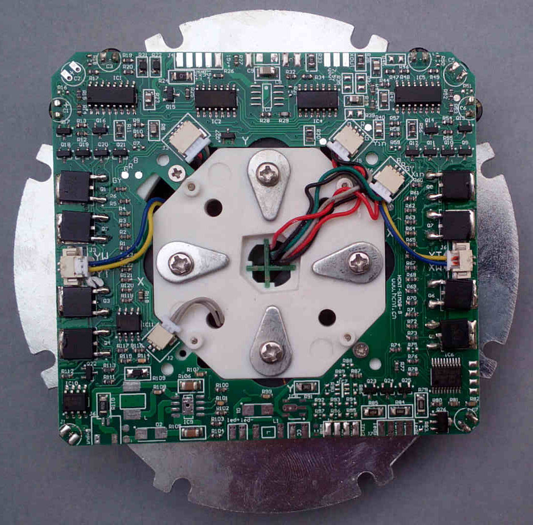
Next, attach the base PCB to the levitation module. Line up the PCBs with the module rotated as shown and support the base board so the track sides level with each other then use the thick solder to bridge the pads indicated.
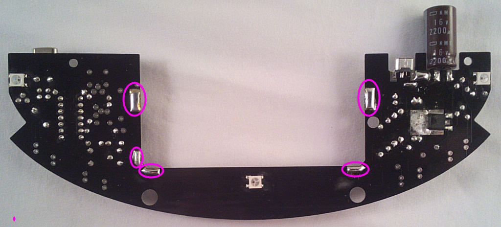
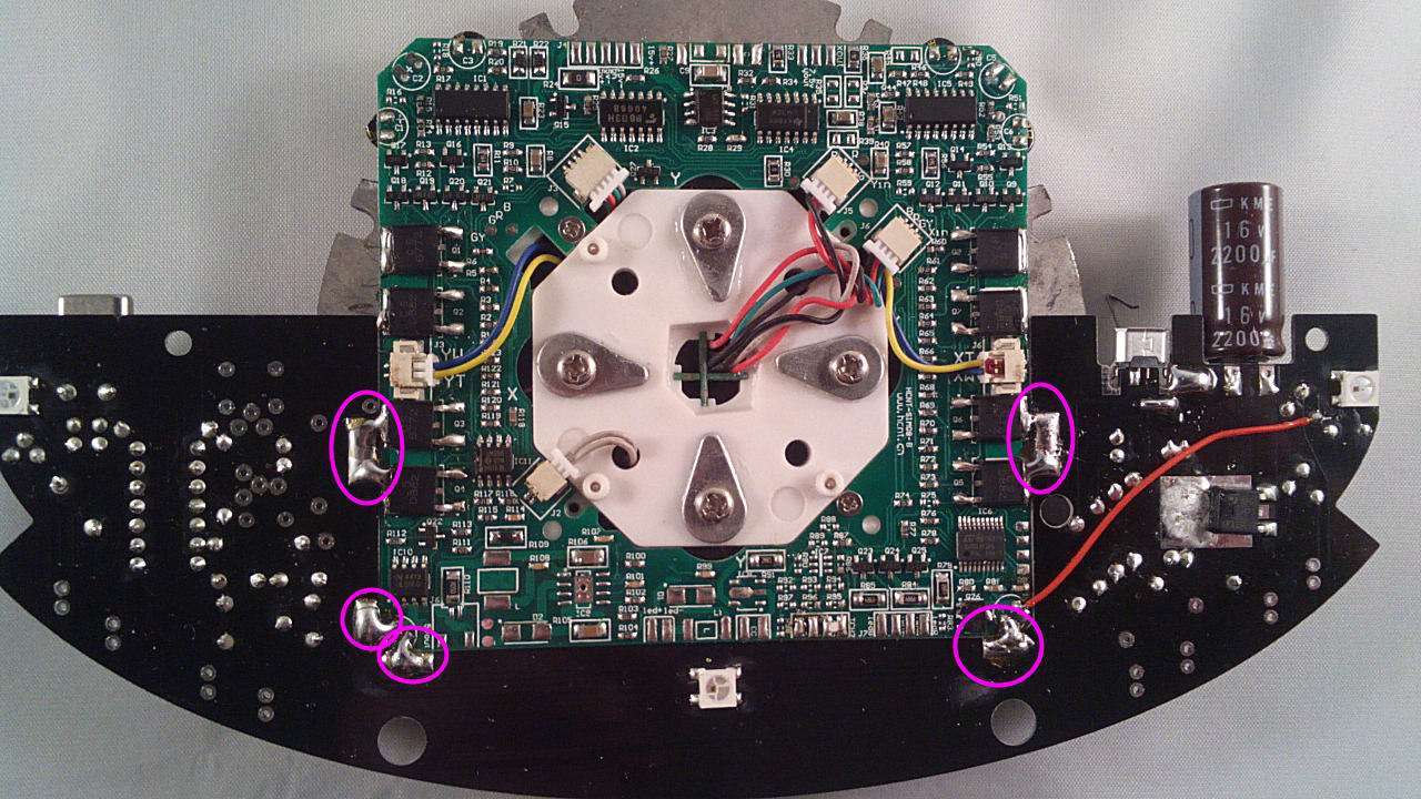
Using an offcut of wire from the 15V plug, link these points under the PCB:
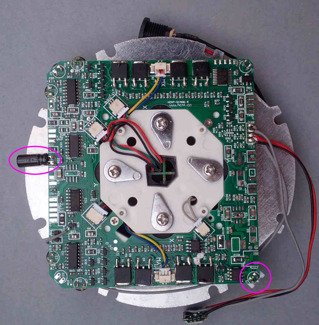
Solder 2 offcuts of wire to the 2 pads just below the USB socket - these are in series with the incoming 15V supply and will be used to monitor current during testing. Connect a multimeter on a 500mA or 1A range to the 2 wires.
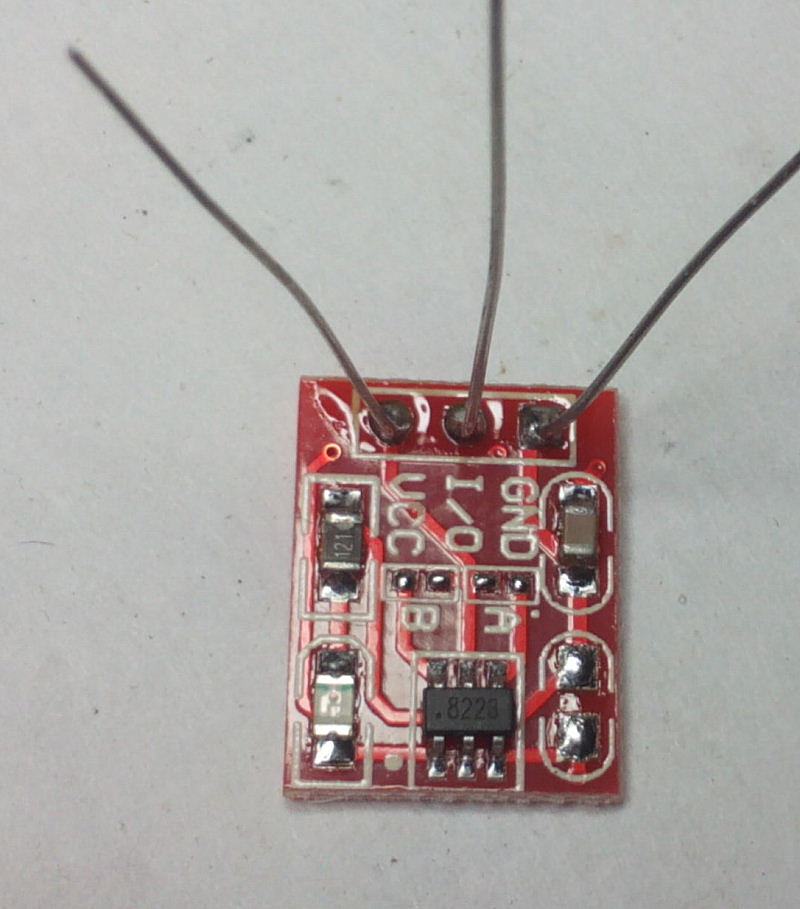
Solder 3 wire offcuts to the touch-switch module connection pads:
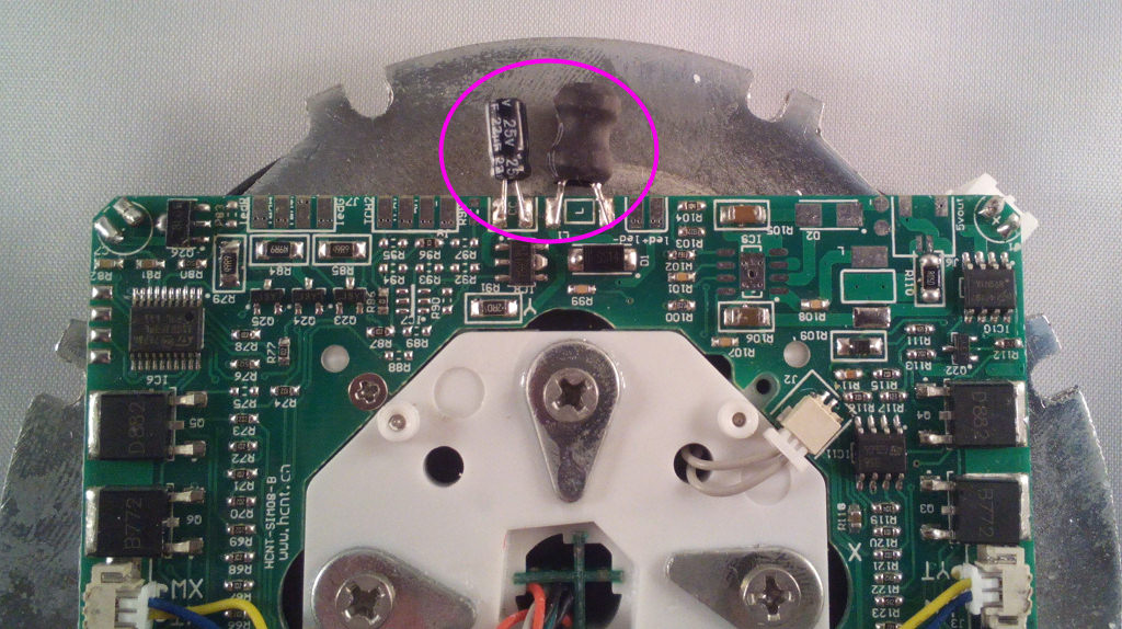
Trim the wires to ablout 1" in length, then solder them to the marked points on these components at the right hand side of the base PCB:
BLUE - GND, RED - VCC, GREEN - I/O. I would also recommend adding a 330-470u 6.3V+ capacitor across Vcc and GND on the module. *NOTE This is needed as the touch switch will activate randomly otherwise so consider it essential.
Feel free to experiment with your own switch - you could add 433mhz remote control for example, the PIC input expects an active low signal.
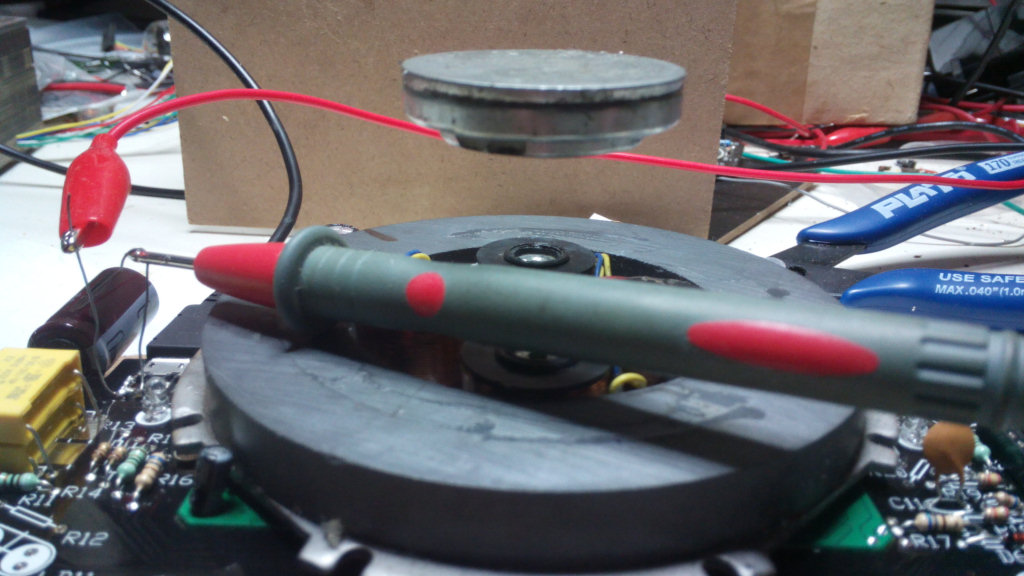
Now it's time for the first power-on test. Connect the base to the power PCB using the supplied micro-USB cable and switch on. The current reading should be about 100mA, more if one of the LEDs randomly decided to light up. It shouldn't be more than about 140-160mA if so.
Switch off and fit IC4, then switch on again. The current reading should be almost the same, the LEDs will flash green for a second then go out. Put your finger near the touch switch, the LED on it should light up and LS1 will start to beep with a tone increasing in frequency the longer the switch is held.
Try carefully floating the small magnet included in the 'relay' kit box, as it's a bit light just now it will tend to slip easily to one side but should still float with care.
Now jump to the coil winding instructions for the rest of the assembly.