2017-05-13T16:15:23+00:00
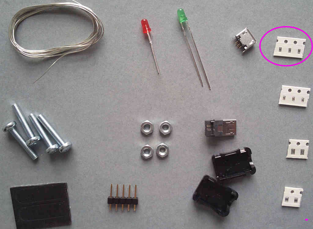
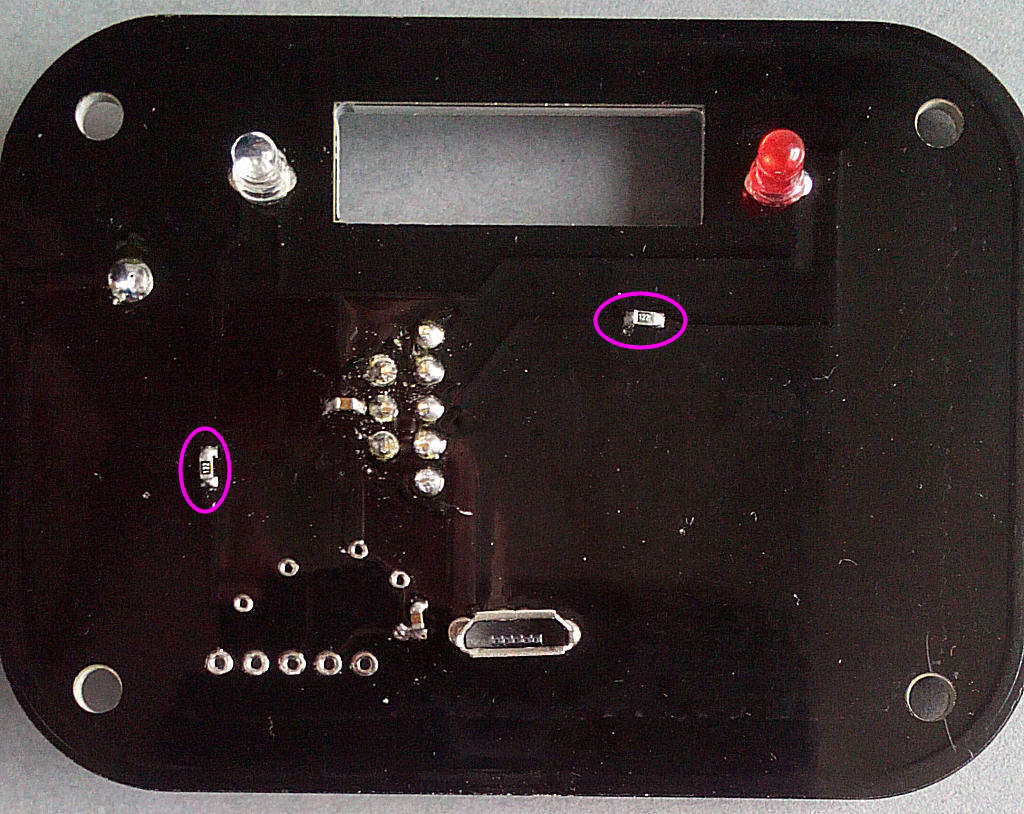
After preparing a suitable working space take the PCB and the 12R resistor (one of the pack of 2 black SMD components, marked 120). Fit this in the location shown:

After preparing a suitable working space take the PCB and the 12R resistor (one of the pack of 2 black SMD components, marked 120). Fit this in the location shown:
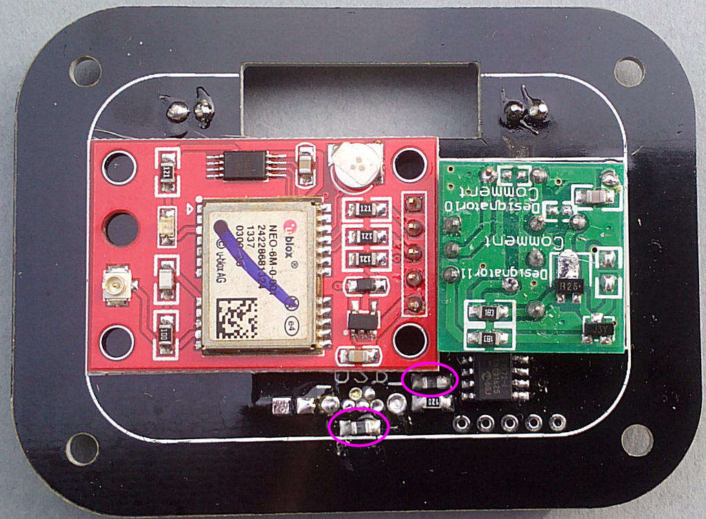
Next the RFI filters (two of the pack of 2 grey SMD components). Fit these in the locations shown:
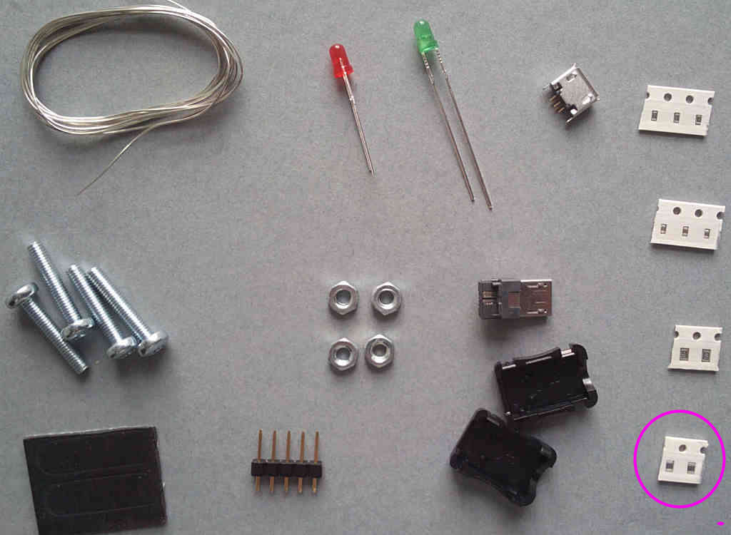
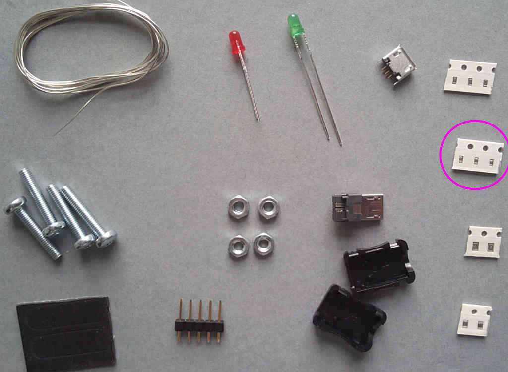
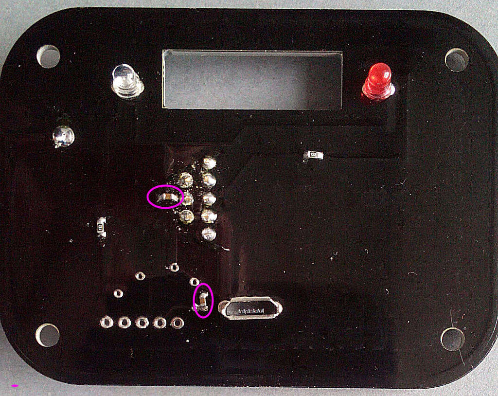
Now for the 1k2 resistors (two of the pack of 3 black SMD components, marked 122). Fit these in the locations shown:
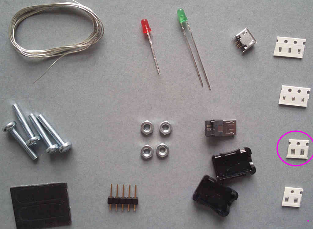
The 0.22u capacitors (two of the pack of 3 brown SMD components). Fit these in the locations shown:
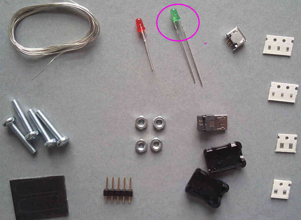
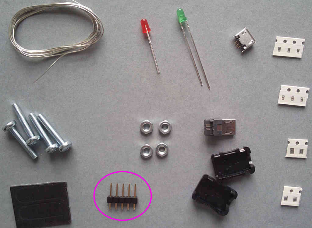
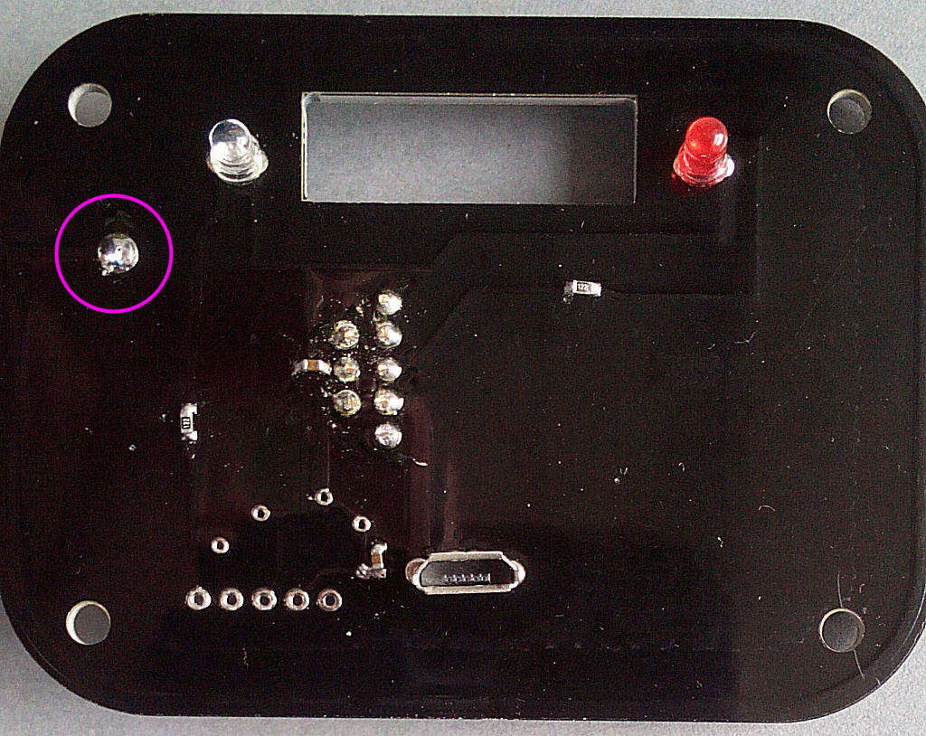
Now for the LEDs - starting with the clear/green. Fit this in the location shown - it's polarised and the SHORT LEG faces to the RIGHT:

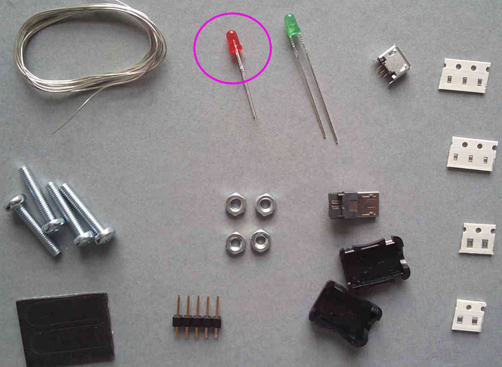
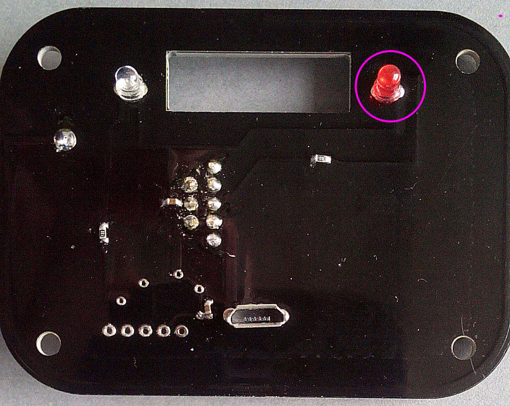
Then the red. Fit this in the location shown - it's polarised and the SHORT LEG faces to the RIGHT:
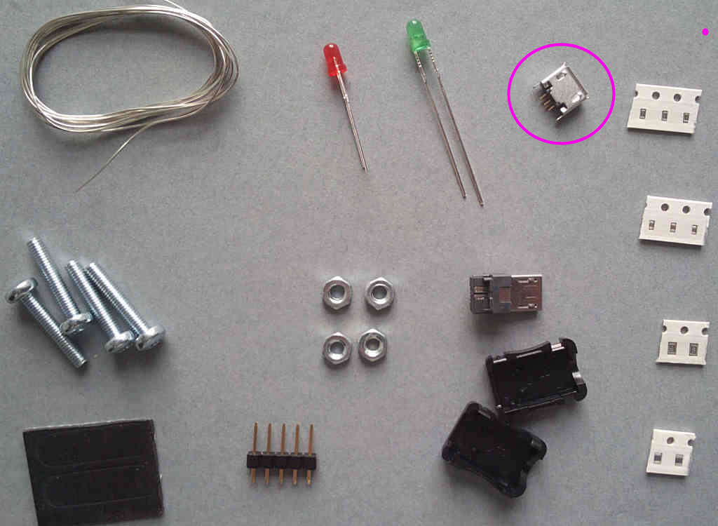
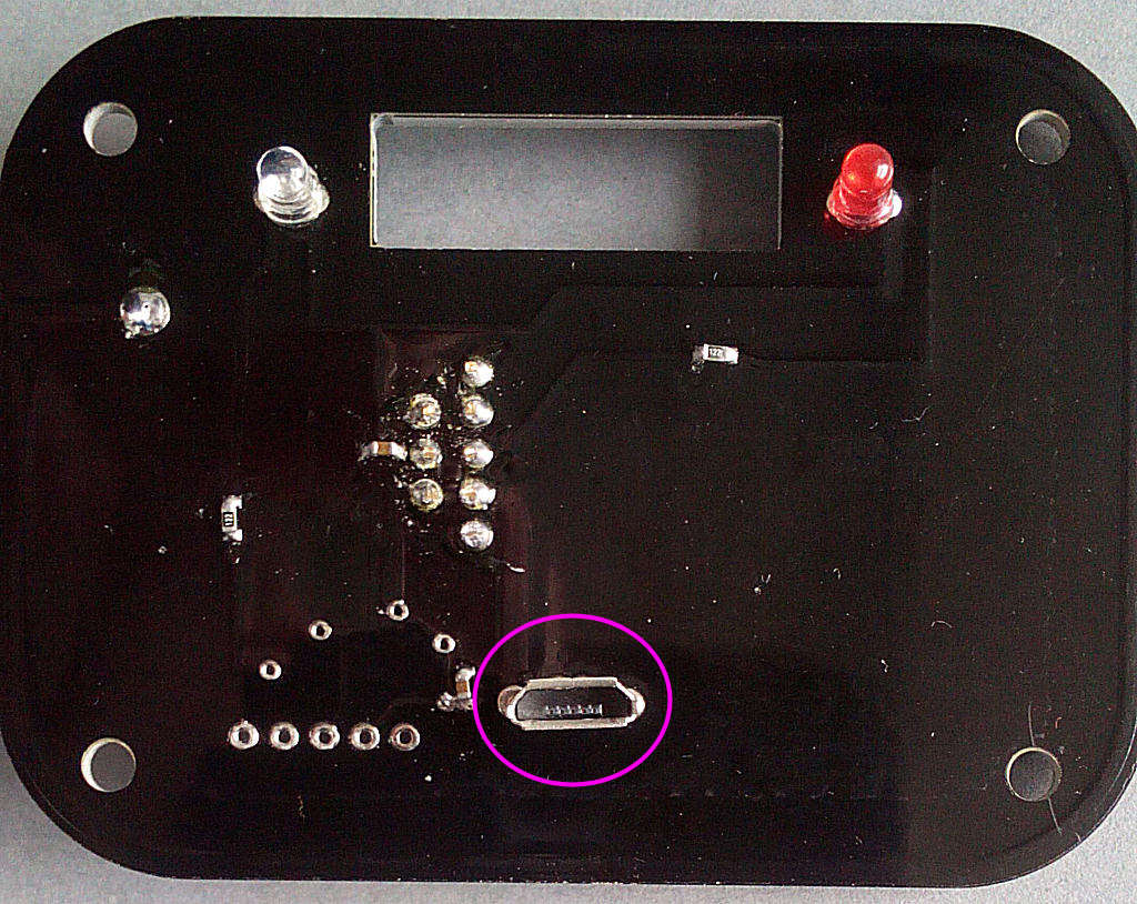
Solder the USB socket next - it's on the same side of the PCB as the LEDs. Make sure you solder the frame leads as well:
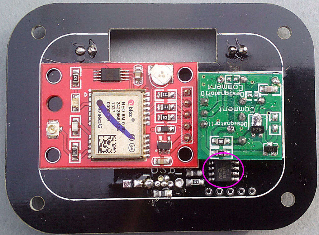
Now the PIC IC - again it's polarised and there's a small dot to indicate pin1. This is the TOP LEFT pin:
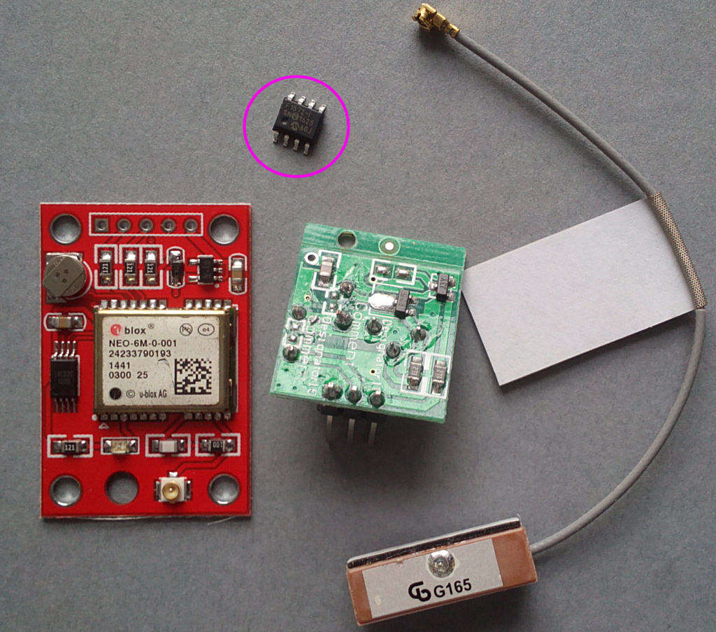
Solder the 5-pin pinstrip onto the GPS module:
Then solder it onto the main PCB - make sure it's on the correct side of the board:

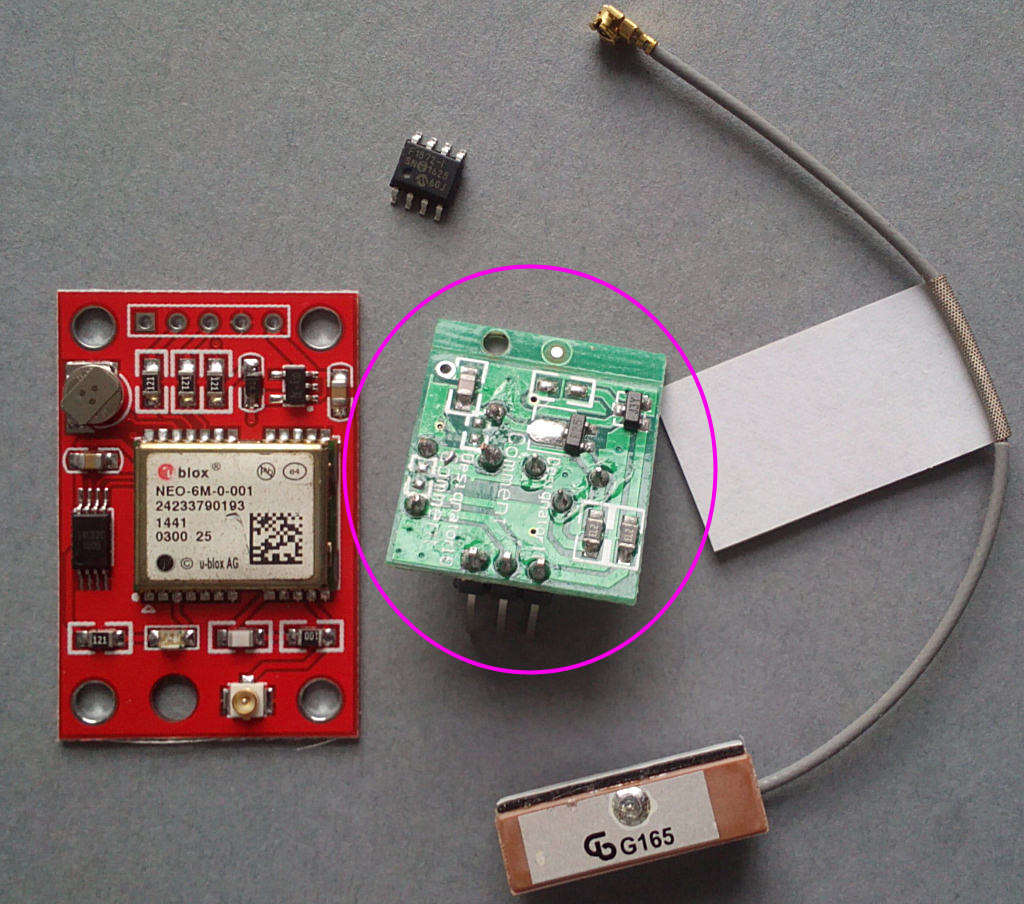
Solder the 433 Tx module onto the PCB next to the GPS module - you'll need to bend the pins slightly to make it fit:
Note that some of the modules may have an extra strip of PCB material attached - you can see it in the photo along the top of the module. This can be snapped off along the score line and will need to be removed for it to fit in the case.
Solder a piece of wire from the pad on the top right corner of the Tx module to the PCB - there's a hole almost directly below it:

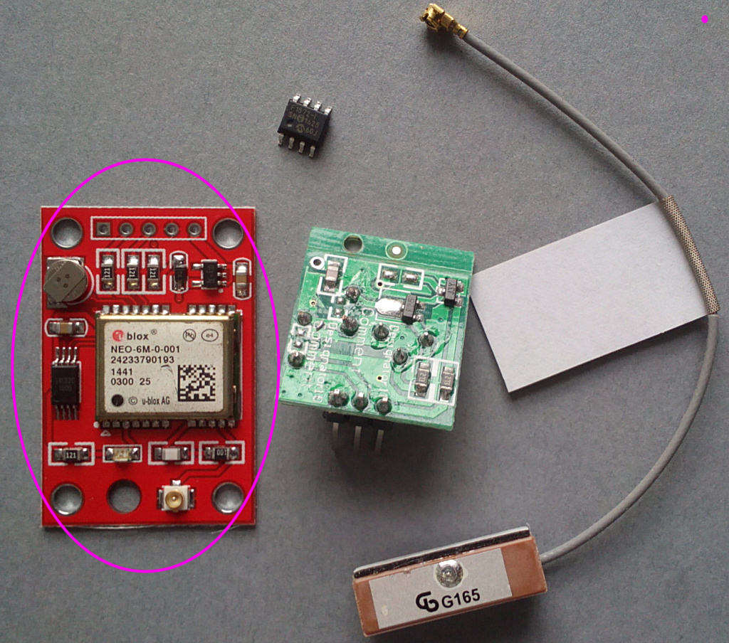
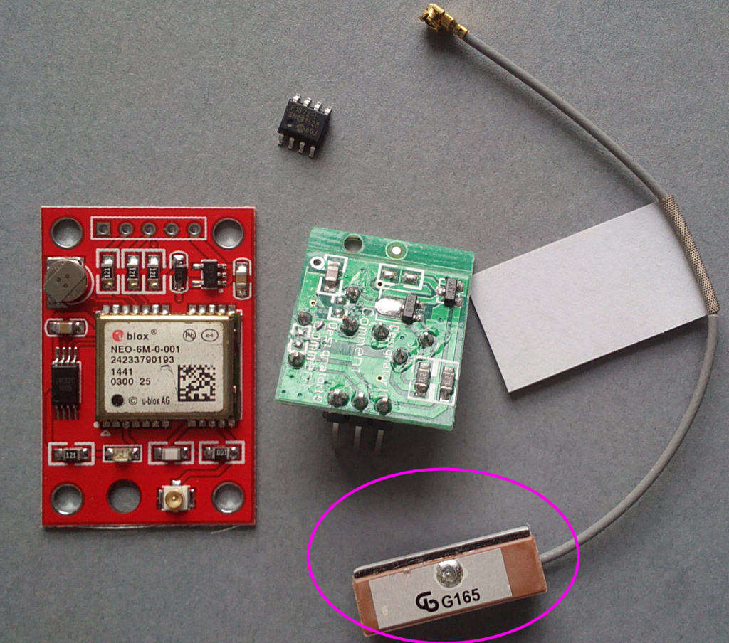
Connect the antenna to the GPS module:
DO NOT CONNECT THE GPS MODULE TO THE POWER SUPPLY/CONTROLLER PCB!
Time to test it - connect a voltmeter across the 12R resistor (you'll probably need to solder a couple of wire legs onto it to attach the probes). Connect it to the the 5V US-plug USB power supply using the included micro USB lead (For UK power supplies see the instructions on fitting the micro USB plug) and switch on, monitoring the voltage reading.
It should be around 0.5-1V, if it's significantly more switch off and look for mistakes.
You should now have a red LED on the GPS module and the red LED on the PCB lit. Set it up where it can receive a GPS signal. Agter about a minute the module red LED should start flashing, indicating packets received. The PCB red LED will start to flicker. Agter another minute or so the green LED will start to flash once a second - this indicates valid time packets have been received and are being retransmitted. After 3 minutes it will change to short flashes, this indicated valid time received but not retransmitted. Once every 250 seconds it will transmit, indicated by a longer flash.